Description
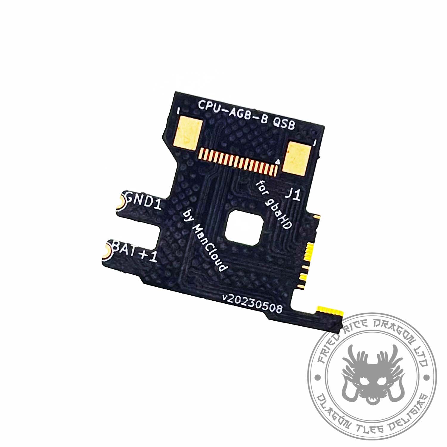
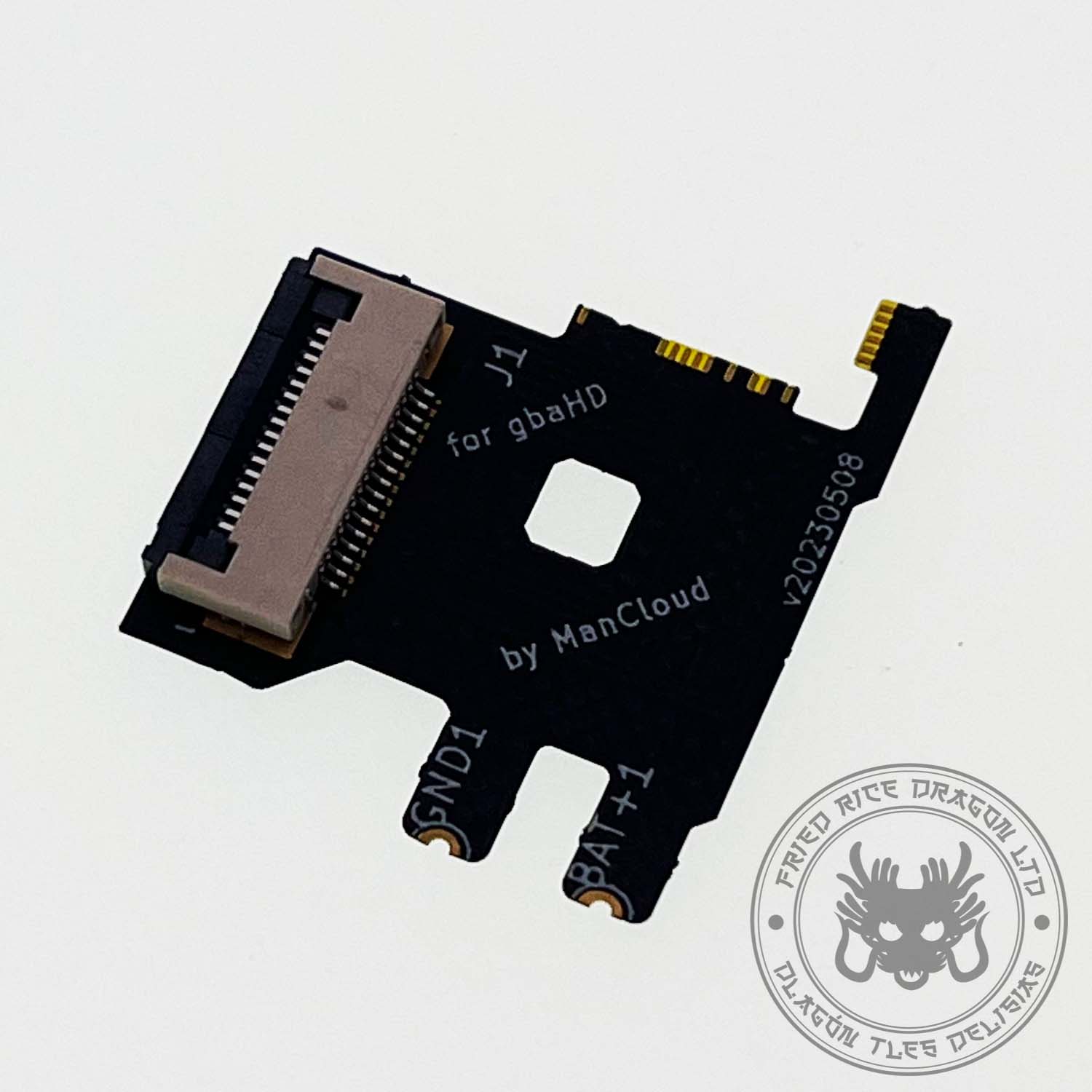
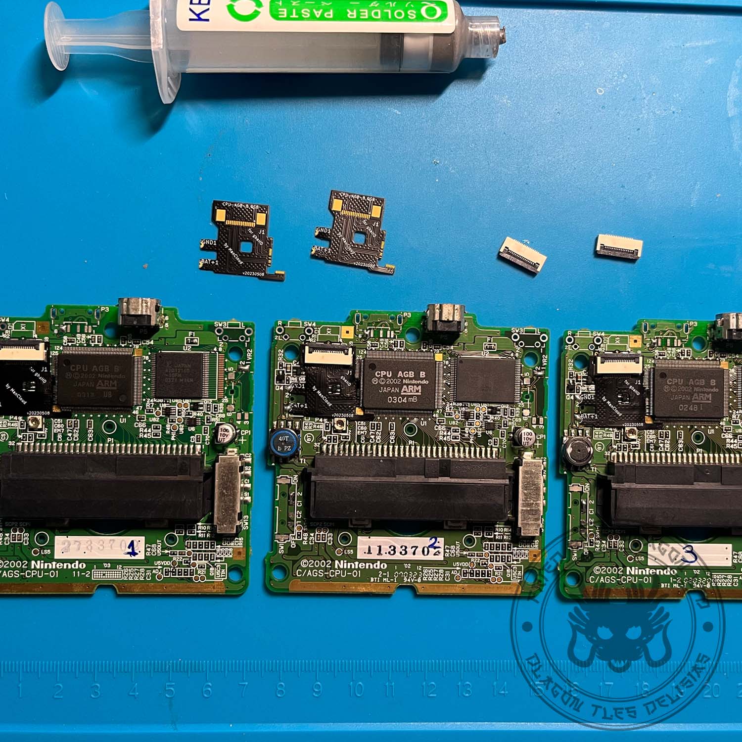
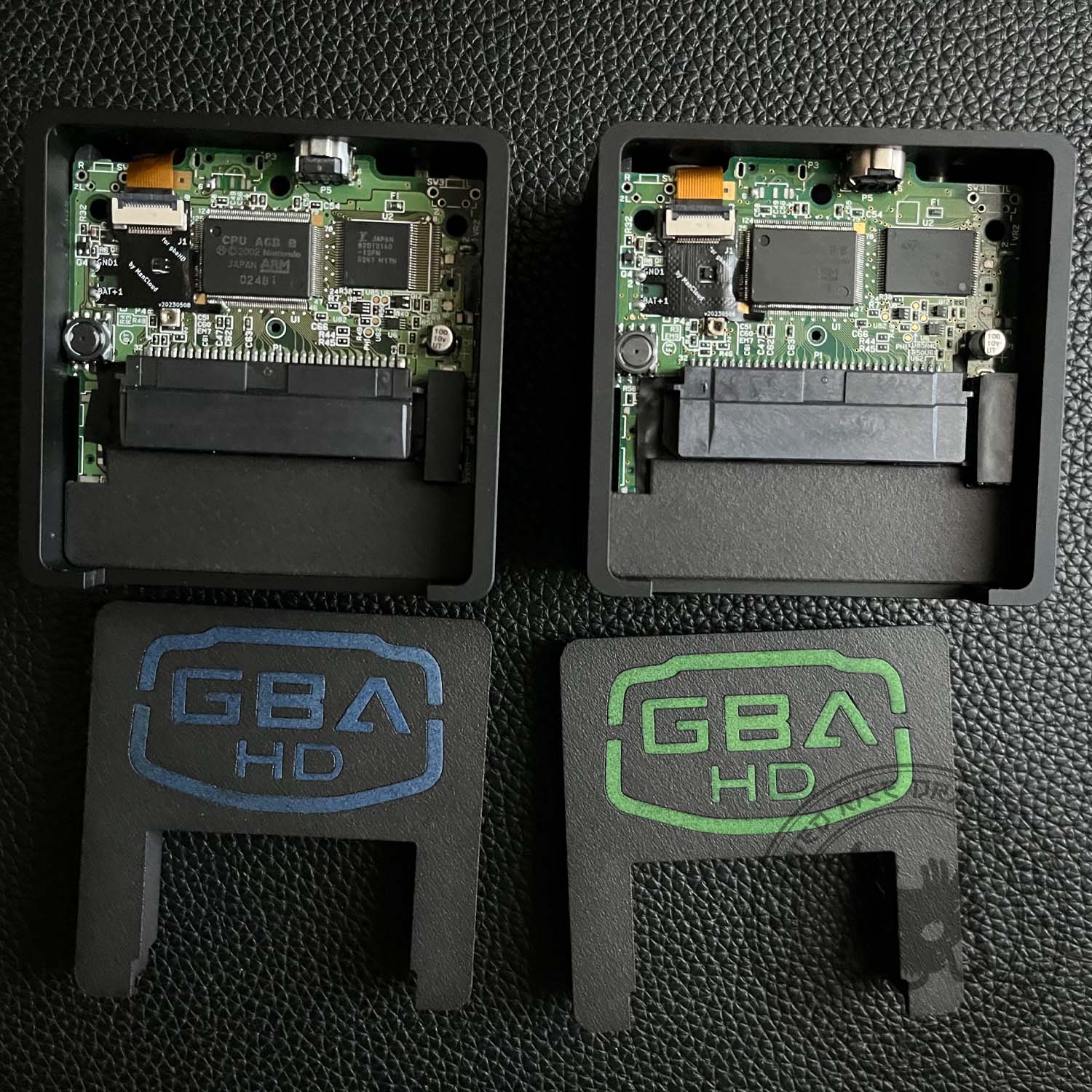
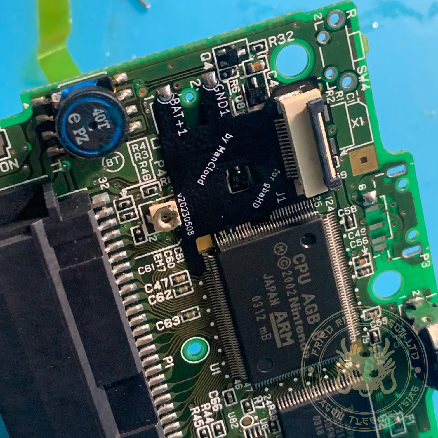
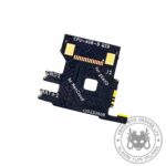
With Mancloud’s SP CPU Flex cable you’ll be able to make a completely wire-free installation.
Before, it was really difficult to properly manufacture this flex cable due to its tiny size, however, thanks to some tweaks to its design by Mancloud, now we have a very high-quality flex cable for our SP gbaHDs.
Remember that unlike the regular wired installation with the breakout board, using the Flex CPU requires the SP power switch to be set to ON.
Made with much thicker gold and copper layers than normal to be able to take the amounts of heat that this installation will require.
The 16pin FPC connector is included with the flex cable, but it is not provided pre-soldered. This is to deter unqualified people from even thinking of trying this method.
This installation method is only for very experienced modders and should NEVER be attempted by unqualified people. For most people, it’ll help to use a microscope for soldering and a multimeter at the end to check everything is right. We warn you beforehand and we take no responsability for whatever you break. The pitch of this flex cable is tiny and it goes directly soldered onto the already tiny SP CPU legs. Attemp this only if you really know what you are doing, otherwise, you’ll probably end up ruining your GBASP console.
—————————————————————————–
NOTE 1: Tested to work with the following Gameboy Advance SP CPU Revisions:
AGS-CPU-01, AGS-CPU-10, AGS-CPU-11, AGS-CPU-21, AGS-CPU-30, AGT-CPU-01
NOTE 2: It is strongly recommended to use lead-free solder for this installation, lots of flux and very, very little solder. It is easy to create shorts on the CPU on places under the flex that you won’t be able to see.
When you are completely done testing, cleaning, etc, you can add a little drop of UV resin to keep the joints rock solid. UV resin is easy to remove in one piece with a heatgun and won’t damage anything on the PCB.
NOTE 3: To seat the flex up, apply a small piece of double-sided tape where the FPC connector will seat and then try to center the flex’s pins with the CPU. Once you align it properly, stick it with the double-sided tape to the motherboard and then solder the pins on the left to ground it in place and to keep it properly aligned. A pair of pliers will help you to slightly bend the flex to make contact with the CPU pins.
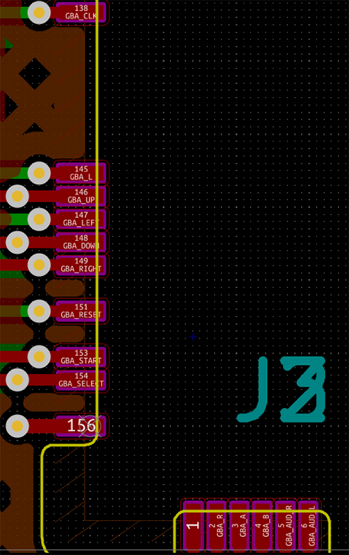
NOTE 4: Once you get the SP booting after soldering the flex, aside of using a multimeter to ensure everything is okay, you can use the ROM “AGS Aging” on a flashcart and perform a button check to see that everything works as intended. In case of shorts that you may have overlooked, the AGS Aging will easily show you what’s shorted together when you push buttons as they’ll register together or will probably go nuts if the short is somewhere else on the CPU. You can follow the next diagram to guide yourself (courtesy of Mancloud).
